CLUTCH: FUNCTION, WORKING AND CLASSIFICATIONS
The clutch is a mechanical device, which is used to connect a driving shaft to driven shaft so that they can be engaged and disengaged at the will of the operator. They used to start and stop a part of a system without stopping remaining parts of the power transmission system. They are used mostly in automobiles. The clutch allows to insert a gear system (gearbox) between engine and wheels, facilitate gear changing when the engine is running. Other applications of clutch: Torque limiting clutch in the electric screwdriver, bicycles pedal ratcheting.
Function of the Clutch
1. Function of transmitting the torque from the engine to the drivetrain.
2. Smoothly deliver the power from the engine to enable smooth vehicle movement.
3. Perform quietly and to reduce drive-related vibration.
4. Protect the drivetrain when given the inappropriate use. Given the situation, the Exedy clutch will fail when giventhe inappropriate use inturn to protect the rest of the drivetrain, similar to the function of an electric fuse.
Requirements of a good clutch
1. The clutch should be able to transmit 1.25 to 1.50 times the maximum engine torque.
2. The clutch material should have good coefficient of function.
3. Lot of heat is generated due to the relative motion between the flywheel, pressure plate and clutch plate during clutch operation. This heat needs to be quickly dissipated, otherwise high temperature can damage clutch components.
4. The clutch should have low moment of inertia, otherwise the clutch will keep spinning at high speed even during gear changing.
5. Vibration and Jerk absorption. The clutch should be able to take up sudden jerks encountered when the clutch plate comes in contact with the rotating flywheel.
6. The clutch should be dynamically balanced or it will lead to vibrations at high speeds.
7. The operation of the clutch pedal should be easy for the operator and not tiresome, especially for operating for long durations.
Clutch Facing Material
While selecting material for clutch facing, it is to be kept in mind that the material should have high coefficient of friction, low heat generation and quick dissipation of generated heat. These qualities are counter to each other. Hence a tradeoff has to be reached. Most common materials that can be used are as follows:
* Leather -Coefficient of friction of dry leather on iron is 0.27
* Cork -Coefficient of friction on dry steel is 0.32
* Fabric -Coefficient of friction on dry steel is 0.4, but these cannot be used at high temperature.
* Asbestos -Coefficient of friction on dry steel is 0.2, has good anti-heat properties, but is harmful for human health.
* Ferodo Material -This material is based on asbestos and has a coefficient of friction 0.35.
HOW CLUTCH WORKS

It transmits engine power to the gearbox, and allows transmission to be interrupted while a gear is selected to move off from a stationary position, or when gears are changed while the car is moving.
Most cars use a friction clutch operated either by fluid (hydraulic) or, more commonly, by a cable.
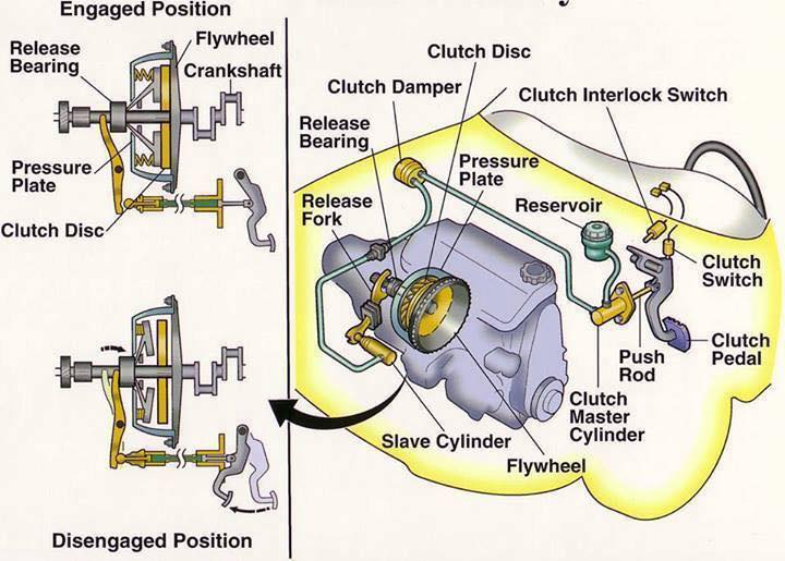
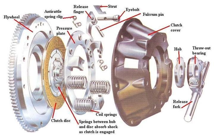
When a car is moving under power, the clutch is engaged. A pressure plate bolted to the flywheel exerts constant force, by means of a diaphragm spring, on the driven plate.
Earlier cars have a series of coil springs at the back of the pressure plate, instead of a diaphragm spring.
The driven (or friction) plate runs on a splined input shaft, through which the power is transmitted to the gearbox. The plate has friction linings, similar to brake linings, on both its faces. This allows the drive to be taken up smoothly when the clutch is engaged.
When the clutch is disengaged (pedal depressed), an arm pushes a release bearing against the centre of the diaphragm spring which releases the clamping pressure.
The outer part of the pressure plate, which has a large friction surface, then no longer clamps the driven plate to the flywheel, so the transmission of power is interrupted and gears can be changed.
Clutch engaged
The diaphragm spring is holding the driven plate.
Clutch disengaged
The release bearing has depressed the diaphragm spring.
When the clutch pedal is released, the thrust bearing is withdrawn and the diaphragm-spring load once again clamps the driven plate to the flywheel to resume the transmission of power.
Some cars have a hydraulically operated clutch. Pressure on the clutch pedal inside the car activates a piston in a master cylinder, which transmits the pressure through a fluid-filled pipe to a slave cylinder mounted on the clutch housing.
The slave-cylinder piston is connected to the clutch release arm.
CLUTCH TYPES
These may classified as follow:
According to the method of transmitting torque:
1. Positive clutch (Dog clutch):
In the positive clutch, grooves are cut either into the driving member or into the driven member and some extracted parts are situated into both driving and driven member. When the driver releases clutch pedal then these extracted parts insert into grooves and both driving and driven shaft starts revolve together. When he push the clutch pedal these extracted parts come out from grooves and the engine shaft revolve itself without revolving transmission shaft.
Application of positive clutch
They have very limited use. However, they have some application where the synchronous drive is required.
Advantages and disadvantages of positive clutch
Advantages
1. They do not slip.
2. They can transmit large torque.
3. Develop no heat during engagement and disengagement because of rigid interlocking (no friction).
Disadvantages
1. Engagement of clutch cannot be possible at high speed.
2. While starting some relative motion may be required to engage.
2. Friction clutch:
In this types of clutches, friction force is used to engage and disengage the clutch. A friction plate is inserted between the driving member and the driven member of the clutch. When the driver releases the clutch pedal, the driven member and driving member of clutch, comes in contact with each other. A friction force works between these two parts. So when the driving member revolves, it makes revolve the driven member of clutch and the clutch is in engage position. This type of clutch is subdivided into four types according to the design of the clutch.
Advantages of friction clutch

1. Smooth engagement and minimum shock during the engagement.
2. Friction clutch can be engaged and disengaged when the machine is running since they
have no jaw or teeth.
3. Easy to operate.
4. They are capable of transmitting partial power.
5. Friction clutch can act as a safety device. They slip when the torque exceeds a safe value,
thus safeguards the machine.
6. Frequent engagement and disengagement is possible
Requirement of good friction clutch
1. The following are considered during the design of the friction clutch.
2. The coecient of friction of contact surface should be high enough to hold the load with a minimum amount of axial force. It should not require an external force to carry the burden.
3. The moving parts of the clutch should be lightweight to minimize the inertia load at high speed.
4. Heat generated at contacting surface should dissipate rapidly.
5. It should have provision for taking up the wear of contact.
6. Guard the projecting parts by covering and provide a provision for easy repair.
Requirements of material used for friction clutch
1. The actual contact surface of the friction clutch is the friction lining. Linings are subjected to severe rubbing during a machine run. There are many factors that decide the material
for lining is viable or not. However, the lining material should have certain qualities.
2. It should have a relatively high and uniform coecient of friction under all service conditions.
3. High resistance to wear.
4. It should withstand a high compressive load.
5. It should be chemically inert, oil and moisture have no eect
on them.
6. High heat conductivity. It should rapidly dissipate the heat generated.
7. It should have excellent compactibility with cast iron facing.
A.) Cone clutch:
It is a friction type of clutch. As the name, this type of clutch consist a cone mounted on the driven member and the shape of the sides of the flywheel is also shaped as the conical. The surfaces of contact are lined with the friction lining. The cone can be engage and disengage from flywheel by the clutch pedal.
B.) Single plate clutch:
In the single plate clutch a flywheel is fixed to the engine shaft and a pressure plate is attached to the gear box shaft. This pressure plate is free to move on the spindle of the shaft. A friction plate is situated between the flywheel and pressure plate. Some springs are inserted into compressed position between these plates. When the clutch pedal releases then the pressure plate exerts a force on the friction plate due to spring action. So clutch is in engage position. When the driver pushes the clutch pedal, due to its mechanism, it serves as the disengagement of clutch.
Main components of a Single Plate Axial Spring type friction clutch
1. Flywheel: It is connected to the engine crankshaft and is used to store the energy.
2. Clutch Plate: It consists of a steel disc with the centre splined. Frictional material is mounted (riveted) around the circumference of the steel disc.
3. Pressure Plate: The pressure plate pushes the clutch plate onto the flywheel due to spring pressure so that the clutch plate on one side and the flywheel on the other.
4. Axial Springs: Axial springs provide the clamping force due to which the power can be transmitted from the flywheel to the clutch plate.
5. Clutch cover:It isnot only covers the clutch components, but also provides motion from the flywheel to the pressure plate.
6. Clutch release system:it consists of those components which are required for engaging -disengaging the power transmission to the clutch plate.
C.) Multi-plate clutch:
Multi-plate clutch is same as the single plate clutch but there is two or more clutch plates are inserted between the flywheel and pressure plate. This clutch is compact then single plate clutch for same transmission of torque.
Advantages and application of dual clutch
* Torque transmission can be accomplished without interruption torque distribution to the driven road wheels. It replaces the torque converter used in conventional epicyclic-geared automatic transmissions.
* Gears shift can be done very smoothly and eortlessly
when compared to single plate automatic transmission.
* Skip gear without interruption.
* DCT is quick, Fastest gear shifting available to road car transmission. It can shift gear even faster than professional racing driver using a manual transmission.
* High eciency and Fuel economy compared to other automatic shifting.
D.) Diaphragm clutch:
This clutch is similar to the single plate clutch except diaphragm spring is used instead of coil springs for exert pressure on the pressure plate . In the coil springs, one big problem occur that these springs do not distribute the spring force uniformly. To eliminate this problem, diaphragm springs are used into clutches. This clutch is known as diaphragm clutch.
3. Hydraulic clutch:
This clutch uses hydraulic fluid to transmit the torque.
Advantages-
* More flexible as you can put it in any place
* More reliable
* Self adjust
Diasdvantages-
* Pipes can rot
* Got to use correct fluid
According to their design, this clutch is subdivided into two types.
A.) Fluid coupling:
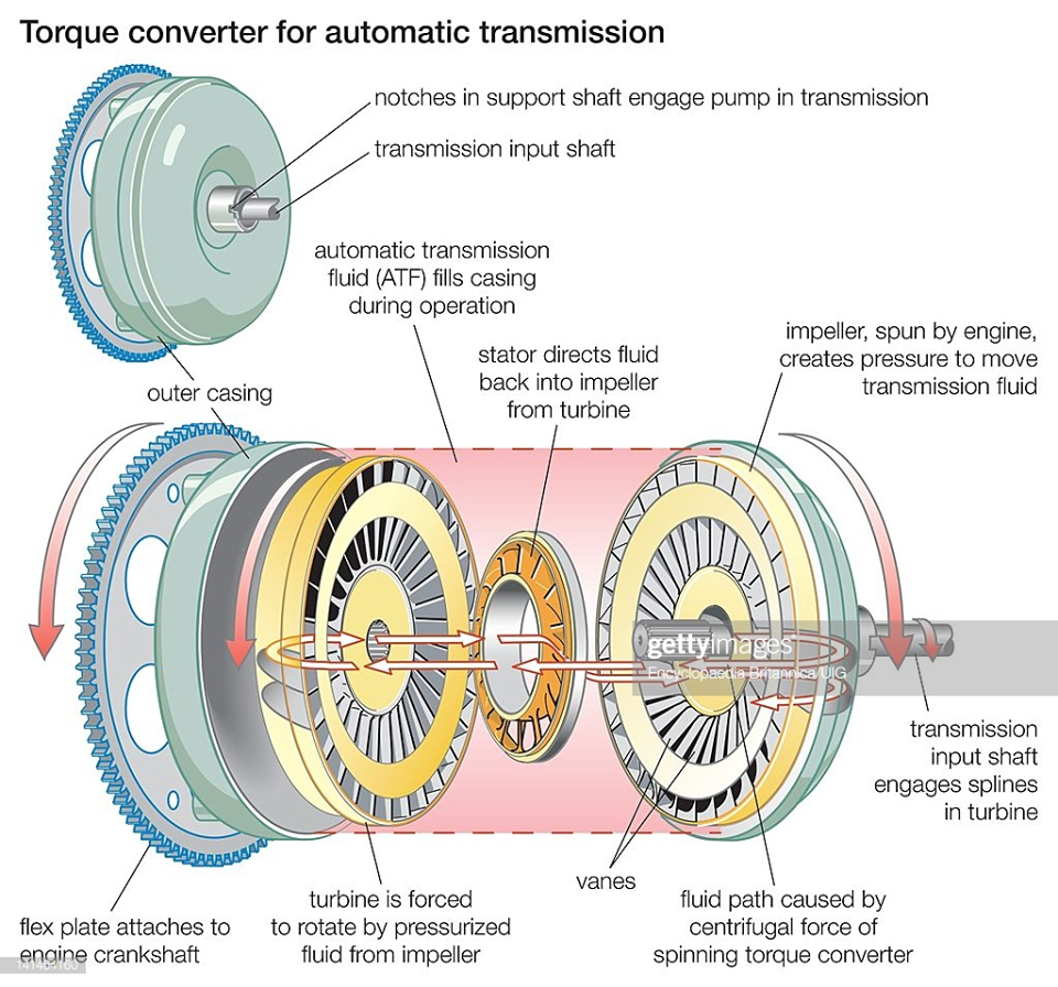
It is a hydraulic unit that replaces a clutch in a semi or fully automatic clutch. In this type of clutch, there is no mechanical connection between driving member and driven member. A pump impeller is blotted on a driving member (Engine) and a turbine runner is bolted on the driven member (Gearbox). Both the above unit is enclosed into single housing filled with a liquid. This liquid serve as the torque transmitter from the impeller to the turbine. When the driving member starts rotating then the impeller also rotates and through the liquid outward by centrifugal action. This liquid then enters the turbine runner and exerts a force on the runner blade. This make the runner as well as the driven member rotate. The liquid flows to the runner then flows back into the pump impeller, thus complete the circuit. It is not possible to disconnect to the driving member to the driven member when the engine is running. So the fluid coupling is not suitable for ordinary gear box. It is used with automatic or semi-automatic gear box.
B.) Hydraulic torque converter:
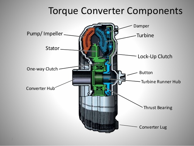
Hydraulic torque converter is same as the electric transformer. The main purpose of the torque converter is to engage the driving member to driven member and increase the torque of driven member. In the torque converter, an impeller is bolted on the driving member, a turbine is bolted on the driven member and a stationary guide vanes are placed between these two members. This all parts are enclosed into single housing which filled with hydraulic liquid. The impeller rotates with the driven member and it through the liquid outward by centrifugal action. This liquid flowing from the impeller to turbine runner exerts a torque on the stationary guide vanes which changes the direction of liquid, thereby making possible the transformation of torque and speed. The difference of torque between impeller and turbine depends upon these stationary guide vanes. The hydraulic torque converter serves the function of clutch as well as the automatic gear box.
According to the method of engaging force:
1. Spring types clutch:
In this types of clutches, helical or diaphragm springs are used to exert a pressure force on the pressure plate to engage the clutch. These springs are situated between pressure plate and the cover. These springs are inserted into compact position into the clutch. So when it is free to move between these two members, it tends to expand. So it exert a pressure force on the pressure plate thus it brings the clutch in engage position.
2. Centrifugal clutch:
As the name implies, in the centrifugal clutch, centrifugal force is used to engage the clutch. This type of clutch does not require any clutch pedal for operating the clutch. The clutch is operated automatically depending upon the engine speed. It consist a weight pivoted on the fix member of clutch. When the engine speed increase the weight fly of due to the centrifugal force, operating the bell crank lever, which press the pressure plate. This makes the clutch engage.
3. Semi-centrifugal clutch:
One big problem occur in centrifugal clutch is that they work sufficient enough at higher speeds but at lower speed they don’t do their work sufficiently. So the need of another type of clutch occurs, which can work at higher speed as well as at lower speed. This type of clutch is known as semi-centrifugal clutch. This type of clutch uses centrifugal force as well as spring force for keeping it in engaged position. The springs are designed to transmit the torque at normal speed, while the centrifugal force assists in torque transmission at higher speeds.
4. Electro-magnetic clutch:
In the electromagnetic clutch electro-magnate is used to exert a pressure force on pressure plate to make the clutch engage. In this type of clutch, the driving plate or the driven plate is attached to the electric coil. When the electricity is provide into these coils then the plate work as the magnate and it attract another plate. So both plates join when the electricity provides and the clutch is in engage position. When the driver cut the electricity, this attraction force disappear, and the clutch is in disengage position.
According to the method of control:
1. Manual clutch:
In this type, clutch is operated manually by the driver when he need or when shifting the gear. This type of clutch uses some mechanical, hydraulic or electrical mechanism to operate the clutch. All friction clutches are include in it.
2. Automatic clutch:
These types of clutches used in modern vehicle. This clutch has self operated mechanism which control the clutch when the vehicle need. Centrifugal clutch, hydraulic torque converter and fluid coupling includes in it. This type of clutch is always used with the automatic transmission box.
Mechanical Engineering World
